
Eaton
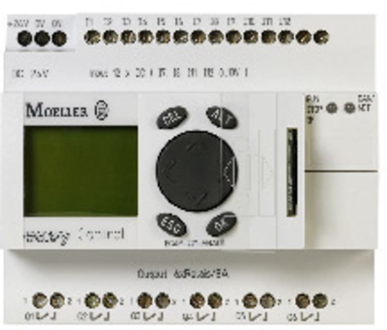
EC4P, 6 Relay Q, displ. 1AO
Part numberEC4P-221-MRAD1EAN / GTIN4015081061679HS code8536.90
Control & Automation
Relays & Timers
MOQ:1
Pricing
Request a quote
We reply within 24 hours
Overview
Eaton EC4P, 6 Relay Q, displ. 1AO (part number EC4P-221-MRAD1) is listed under Control & Automation / Relays & Timers. HS code: 8536.90; Sales unit: pcs; Eaton catalogue number: 106397; Depth: 72 mm; Height: 90 mm; Width: 107.5 mm.
Technical Specifications
- Manufacturer part number (MPN)
- EC4P-221-MRAD1
- EAN / GTIN
- 4015081061679
- HS code
- 8536.90
- Sales unit
- pcs
- Eaton catalogue number
- 106397
- Depth
- 72 mm
- Height
- 90 mm
- Width
- 107.5 mm
- Weight
- 0.374 kg
- Certifications
- UL File No.: E135462; CSA File No.: 012528; CSA-C22.2 No. 0-M; UL; IEC/EN 61000-4-2
- Level 3; UL Category Control No.
- NRAQ; CE; CSA; CSA Class No.: 2252-01; UL508; CSA-C22.2 No. 142-M
- Catalog Notes
- Expandable: Inputs/outputs and bus systems
- Constant acceleration
- 2 g, 57 - 150 Hz, according to IEC/EN 60068-2-6, Vibrations
- Constant amplitude
- 0,15 mm, 10 - 57 Hz, according to IEC/EN 60068-2-6, Vibrations
- Drop and topple
- 50 mm Drop height, Drop to IEC/EN 60068-2-31
- Height of fall (IEC/EN 60068-2-32) - max
- 1 m
- Mounting position
- Vertical; Horizontal
- Shock resistance
- 15 g, Mechanical, according to IEC/EN 60068-2-27, Half-sinusoidal shock 11 ms, 18 Impacts
- Air pressure
- 1080 hPa (operation)
- Ambient operating temperature - max
- 55 °C
- Ambient storage temperature - max
- 70 °C
- Ambient operating temperature - min
- -25 °C
- Ambient storage temperature - min
- -40 °C
- Environmental conditions
- Condensation: prevent with appropriate measures; Clearance in air and creepage distances according to EN 50178, UL 508, CSA C22.2, No. 142
- Relative humidity
- 5 - 95 % (non-condensing)
- Bus termination
- EASY-NT-R plug (incl. bus terminating resistor 120 Ω),first and last station, CANopen®
- Character formats
- 8E1, 8O1, 8N1, 8N2, 7E2, 7O2, 7N2, 7E1, PRG interface RS232, Master mode
- Connection type
- RJ45, Ethernet; 2 x RJ45, 8 pole, CANopen®; RJ45, PRG Interface RS232
- Cycle time
- < 0.3 ms, for 1 k of instructions (Bit, Byte), CPU
- Memory
- 4 kByte Input Memory; 14 segments of 16 kByte Program memory data; 4 kByte Output Memory; 8 kByte Retain Memory; 256 kByte Program memory code; 16 kByte Marker Memory
- Number of bytes
- 190 transmission bytes (in a block)
- Number of modules
- Max. 126 (slaves)
- Station
- To DS 301 V4, Control contact rated current, Mode slave, Interfaces
- Write cycles of the retentive memory
- 10,000,000,000 read-write cycles
- Equipment heat dissipation, current-dependent Pvid
- 0 W
- Heat dissipation capacity Pdiss
- 0 W
- Heat dissipation per pole, current-dependent Pvid
- 0 W
- Rated operational current for specified heat dissipation (In)
- 0 A
- Static heat dissipation, non-current-dependent Pvs
- 3.4 W
- Air discharge
- 8 kV
- Burst impulse
- According to IEC/EN 61000-4-4, level 3; 2 kV, Signal cable; 2 kV, Supply cable
- Contact discharge
- 6 kV, Electrostatic discharge (ESD)
- Electromagnetic fields
- 10 V/m (according to IEC EN 61000-4-3)
- Immunity to line-conducted interference
- 10 V (according to IEC/EN 61000-4-6)
- Radio interference class
- Class B (EN 55022); Class B (EN 55011)
- Surge rating
- 2 kV, Supply cables, symmetrical, EASY...AC, power pulses (Surge), EMC; 0.5 kV, Supply cables, symmetrical, EASY…DC, power pulses (Surge), EMC; According to IEC/EN 61000-4-5, power pulses (Surge), EMC
- Features
- Asynchronous, cyclic, acyclic PDO types (operating modes of the slave); Overload and short-circuit protection; 190 received bytes in a block (PRG interface RS232, Master mode)
- Fitted with
- Display; Analog output module; Engineering software; Keypad; Control unit; Power supply; Monitor; Memory unit; Libraries; Documentation; Basic device; Digital input module; Communication module; Other components; easyNet/CANopen® on board; Analog input module; Digital output module; Function module
- Functions
- Building blocks
- Inscription
- Individual inscription possible with EC4-COMBINATION-*
- Processor
- Infineon XC161
- Cable length
- 30 m, screened, Analog inputs; 100 m, unshielded, Digital inputs 24 V DC
- Degree of protection
- IP20
- Display temperature - max
- 55 °C
- Display temperature - min
- 0 °C
- Lifespan, mechanical
- 10,000,000 Operations (Relay outputs); 10,000,000 Operations
- Mounting method
- Top-hat rail fixing (according to IEC/EN 60715, 35 mm); Screw fixing using fixing brackets ZB4-101-GF1 (accessories)
- Overvoltage category
- II
- Pollution degree
- 2
- Rated impulse withstand voltage (Uimp)
- Relay outputs: 6 kV (contact-coil)
- Rated insulation voltage (Ui)
- 250 V
- Rated operational voltage
- 20.4 - 28.8 V DC; 24 V DC (-15 %/+ 20 % - power supply)
- Rated operational voltage (Ue) at AC - max
- 300 V
- Recovery time
- 100 µs
- Resolution
- 0.01 V analog (Analog inputs) 0.01 V DC analog (Analog outputs) 0.01 V digital (Analog inputs) 10 Bit (value 0 - 1023, Analog inputs) 10 Bit (value 0 - 1023, digital, Analog outputs)
- Short-circuit protection
- 16 A, Short-circuit-proof cos ϕ = 0.5 to 0.7, characteristic B16 at 900 A, Contacts, Relay outputs; 16 A, Short-circuit-proof cos ϕ = 1, characteristic B16 at 600 A, Contacts, Relay outputs
- Utilization category
- B 300 Light Pilot Duty, UL/CSA Control Circuit Rating Codes AC; R 300 Light Pilot Duty, UL/CSA Control Circuit Rating Codes DC
- Accuracy
- ± 2, (I7, I8, I11, I12) ± 0.12 V, of actual value, within a single device (Analog Inputs); 2 %, Analog outputs at-25 °C - 55 °C; ± 5 s/day (± 0.5 h⁄year), Real-time clock, normally; ± 3 %, of actual value, two devices (Analog Inputs); 1 %, Analog outputs at 25 °C
- Conversions
- Each CPU cycle for Analog inputs; Each CPU cycle, Analog outputs
- Delay time
- 0.25 ms typ., Digital inputs 24 DC (I5 - I12), Delay time from 0 to 1; 0.02 ms typ., Digital inputs 24 DC (I1 - I4), Delay time from 0 to 1
- Incremental counter
- Counter frequency: ≤ 40 kHz; Signal offset: 90°; Counter inputs: I1
- I2; Reference input
- I3; Pulse shape: Square; Value range: 32 Bit; Input for reference switch: I4; Number of counter inputs: 1 (I1, I2, I3, I4)
- Indication
- LCD-display used as status indication of Digital inputs 24 V DC
- Input
- Voltage (DC)
- Input current
- 3.3 mA (I9 - I10, at 24 V DC, at signal 1); 2.2 mA (I11 - I12, at 24 V DC, at signal 1); 1 mA (Analog inputs); 140 mA; 3.3 mA (I1 - I6, at 24 V DC, at signal 1); 2.2 mA (I7 - I8, at 24 V DC, at signal 1)
- Input impedance
- 11.2 kΩ
- Insulation resistance
- According to EN 50178
- Load resistance
- 1 kΩ
- Making/breaking capacity
- 3600/360 VA (AC, at B 300); 28/28 VA (DC, at R 300)
- Number of inputs (analog)
- 4 (I7, I8, I11, I12)
- Number of inputs (digital)
- 12 (24 V DC); 4 (I7, I8, I11, I12, can also be used as analog inputs); 12; 4 (can also be used as analog inputs)
- Number of outputs
- 6 (relay outputs); 8 Transistor Outputs; Relay outputs in groups of 1
- Number of outputs (analog)
- 1
- Output
- Voltage (DC)
- Output current (mA) - max
- 100 mA
- Parallel switching
- Not permitted
- Rapid counter inputs
- Cable length: ≤ 20 m (shielded); 50 kHz, Counter frequency; 2 (I1, I2) at 16 Bit or 1 (I1) at 32 Bit; 16/32 Bit (value range); Pulse shape: Square
- Rated breaking capacity
- 300000 Operations at AC-15, 250 V AC, 3 A (600 Ops./h); 200000 Operations at DC-13, 24 V DC, 1 A (500 Ops./h)
- Rated operational voltage (Ue) at DC - max
- 300 V
- Relay output
- > 500 mA (Recommended for load: 12 V AC/DC)
- Signal range
- 0 - 10 V DC, Analog inputs; 0 - 10 V DC, Analog outputs
- Switching frequency
- 10 Hz, Relay outputs; 0.5 Hz, Inductive load, Relay outputs; 2 Hz, Resistive load/lamp load, Relay outputs
- Uninterrupted current
- 10 A AC, at 240 V AC (UL/CSA); 5 A AC, max. thermal continuous current cos ϕ = 1 at B 300 (UL/CSA); 1 A DC, at R 300 (UL/CSA); 8 A DC, at 24 V DC (UL/CSA)
- Heat dissipation
- 3.4 W
- Input voltage
- Signal 1: > 15 V DC (I1 - I6, I9 - I10, Digital inputs
- 24 V DC); Signal 1
- > 8 V DC (I7 - I8, I11 - I12, Digital inputs
- 24 V DC); Signal 0
- < 8 V DC (I7 - I8, I11 - I12, Digital inputs
- 24 V DC); Signal 0
- < 5 V DC (I1 - I6, I9 - I10, Digital inputs, 24 V DC)
- Residual ripple
- ≤ 5 %
- Supply voltage at DC - max
- 24 VDC
- Voltage dips
- According to EN 61131-2; ≤ 10 ms
- Protection of an output relay
- Miniature circuit-breaker B16 or fuse 8 A (slow)
- Safe isolation
- 300 V AC, Between coil and contact, According to EN 50178; 300 V AC, Between two contacts, According to EN 50178
- Screwdriver size
- 3.5 x 0.8 mm, Terminal screw
- Terminal capacity (flexible with ferrule AWG)
- 22 - 12
- Terminal capacity (flexible with ferrule)
- 0.2/2.5 mm²
- Terminal capacity (solid AWG)
- 22 - 12
- Terminal capacity (solid)
- 0.2/4 mm²
- Tightening torque
- 0.6 Nm
Standards & Compliance
- HS Code
- 8536.90
Cross References
- EAN 4015081061679
- SAP 1000288815
- Code 81037753
Product Documentation
Document preview: EC4P, 6 Relay Q, displ. 1AO (EC4P-221-MRAD1) — Specification Data Sheet (OEM)
More from Eaton
Catalogue entry last verified: 2026-09-30. A manufacturer datasheet is attached to this entry — confirm application-critical values against it.
Frequently asked questions
- Where can I buy EC4P-221-MRAD1?
- EC4P-221-MRAD1 can be ordered from cballast.com as a Eaton catalogue item: request a quotation on this page or email sales@cballast.com, and the order ships worldwide.
- What is the manufacturer part number for this Eaton product?
- The manufacturer part number is EC4P-221-MRAD1.
- What is the HS code for EC4P-221-MRAD1?
- The customs tariff (HS) code for EC4P-221-MRAD1 is 8536.90.
- Who manufactures EC4P-221-MRAD1?
- EC4P-221-MRAD1 is a Eaton product in the Control & Automation range.
- Is a datasheet available for EC4P-221-MRAD1?
- Yes — the EC4P-221-MRAD1 datasheet can be viewed and downloaded on this page.
- What is the minimum order quantity for EC4P-221-MRAD1?
- The minimum order quantity is 1.
- Is EC4P-221-MRAD1 available?
- Yes — EC4P-221-MRAD1 is available to order: fulfilment is from supplier stock in cBallast's European network, dispatched directly from the warehouse to the customer, with the exact lead time stated in the quotation (reply within 24 hours).