
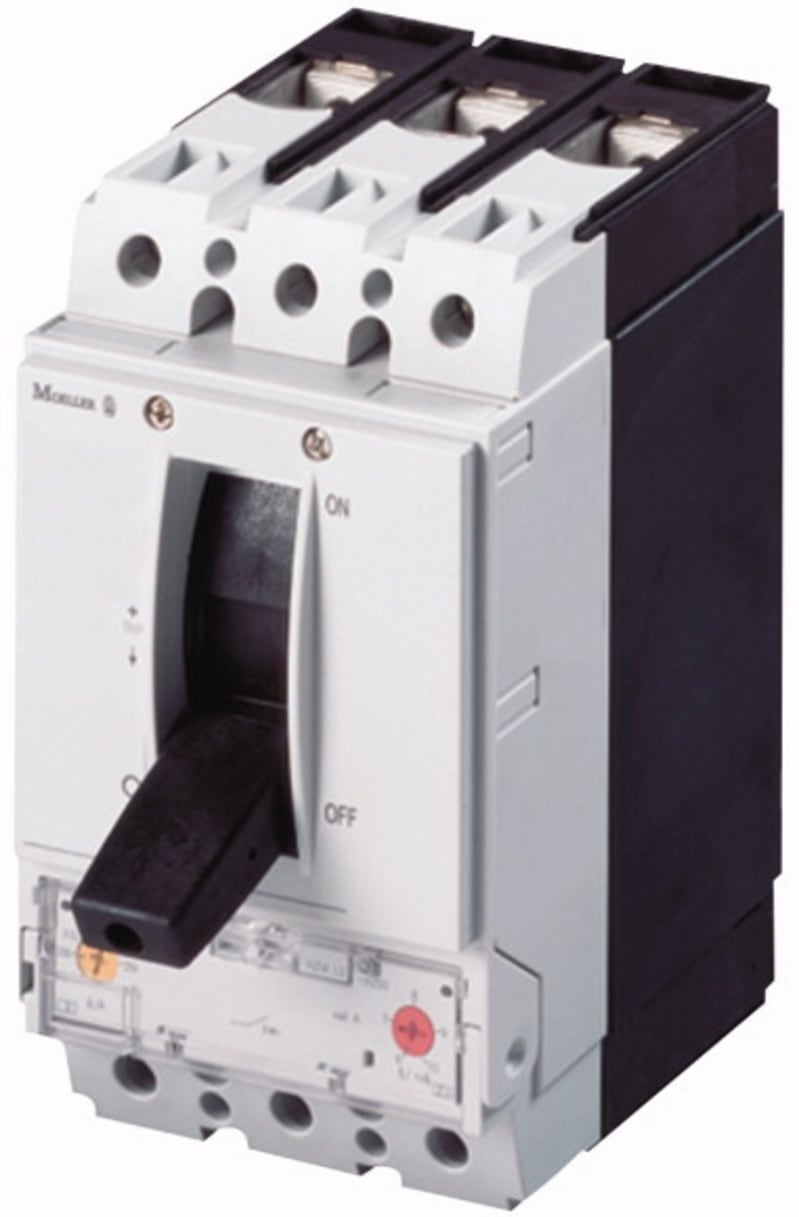
Eaton NZMN2-VE100 Molded-Case Circuit Breaker 3-Pole 100A 50KA
Pricing
Request a quote
We reply within 24 hours
Product Description
Eaton NZM2 molded-case circuit breaker, type NZMN2-VE100. 3-pole, rated current 100 A, breaking-capacity class N, frame size NZM2 (up to 250 A). Rated operational voltage 690 V AC; rated ultimate short-circuit breaking capacity (Icu) 50 kA at 400/415 V AC to IEC/EN 60947-2. Electronic trip unit — adjustable overload and short-circuit protection. Utilization category A, suitable for isolation.
Technical Specifications
- Manufacturer part number (MPN)
- NZMN2-VE100
- Series
- Eaton NZM2 (Moeller series NZM)
- Type
- Molded-case circuit breaker (MCCB)
- Breaking-capacity class
- N (standard breaking capacity)
- Number of poles
- 3-Pole
- Rated current (In)
- 100 A
- Frame size
- NZM2 (up to 250 A)
- Rated operational voltage (Ue)
- 690 V AC
- Rated insulation voltage (Ui)
- 800 V
- Rated ultimate short-circuit breaking capacity (Icu) at 400/415 V AC
- 50 kA
- Trip unit / release
- Electronic trip unit — adjustable overload and short-circuit protection
- Utilization category
- A
- Suitable for isolation
- Yes
- Standard
- IEC/EN 60947-2
- EAN / GTIN
- 4015082591229
- HS code
- 8536.20
- Sales unit
- pcs
- Eaton catalogue number
- 259122
- Depth
- 149 mm
- Height
- 184 mm
- Width
- 105 mm
- Weight
- 2.437 kg
- Compliances
- RoHS conform
- Certifications
- IEC; IEC/EN 60947
- Functions
- Systems, cable, selectivity and generator protection
- Amperage Rating
- 100 A
- Application
- Use in unearthed supply systems at 690 V
- Circuit breaker frame type
- NZM2
- Features
- Protection unit; Motor drive optional
- Release system
- Electronic release
- Ambient operating temperature - max
- 70 °C
- Ambient storage temperature - max
- 70 °C
- Ambient operating temperature - min
- -25 °C
- Equipment heat dissipation, current-dependent
- 8.25 W
- Rated operational current for specified heat dissipation (In)
- 100 A
- Direction of incoming supply
- As required
- Electrical connection type of main circuit
- Screw connection
- Handle type
- Rocker lever
- Instantaneous current setting (Ii) - max
- 1200 A
- Instantaneous current setting (Ii) - min
- 1200 A
- Isolation
- 300 V AC (between the auxiliary contacts); 500 V AC (between auxiliary contacts and main contacts)
- Lifespan, electrical
- 6500 operations at 400 V AC-3; 10000 operations at 400 V AC-1; 7500 operations at 690 V AC-1; 10000 operations at 415 V AC-1; 6500 operations at 415 V AC-3; 5000 operations at 690 V AC-3
- Number of operations per hour - max
- 120
- Overload current setting (Ir) - max
- 100 A
- Overload current setting (Ir) - min
- 50 A
- Overvoltage category
- III
- Pollution degree
- 3
- Rated impulse withstand voltage (Uimp) at auxiliary contacts
- 6000 V
- Rated impulse withstand voltage (Uimp) at main contacts
- 8000 V
- Rated short-circuit making capacity Icm at 240 V
- 50/60 Hz
- 187 kA
- Rated short-circuit making capacity Icm at 400/415 V
- 50/60 Hz
- 105 kA
- Rated short-circuit making capacity Icm at 440 V
- 50/60 Hz
- 74 kA
- Rated short-circuit making capacity Icm at 525 V
- 50/60 Hz
- 53 kA
- Rated short-circuit making capacity Icm at 690 V
- 50/60 Hz
- 40 kA
- Rated short-time withstand current (t = 0.3 s)
- 1.9 kA
- Rated short-time withstand current (t = 1 s)
- 1.9 kA
- Short delay current setting (Isd) - max
- 1000 A
- Short delay current setting (Isd) - min
- 100 A
- Short-circuit release delayed setting - max
- 1000 A
- Short-circuit release delayed setting - min
- 100 A
- Short-circuit release non-delayed setting - max
- 1200 A
- Short-circuit release non-delayed setting - min
- 1200 A
- Short-circuit total breaktime
- < 10 ms
- Voltage rating
- 690 V - 690 V
- Climatic proofing
- Damp heat, constant, to IEC 60068-2-78; Damp heat, cyclic, to IEC 60068-2-30
- Degree of protection
- IP20 (basic degree of protection, in the operating controls area); IP20
- Degree of protection (IP), front side
- IP40 (with insulating surround); IP66 (with door coupling rotary handle)
- Degree of protection (terminations)
- IP00 (terminations, phase insulator and strip terminal); IP10 (tunnel terminal)
- Lifespan, mechanical
- 20000 operations
- Mounting Method
- DIN rail (top hat rail) mounting optional; Fixed; Built-in device fixed built-in technique
- Number of auxiliary contacts (change-over contacts)
- 0
- Number of auxiliary contacts (normally closed contacts)
- 0
- Number of auxiliary contacts (normally open contacts)
- 0
- Position of connection for main current circuit
- Front side
- Protection against direct contact
- Finger and back-of-hand proof to DIN EN 50274/VDE 0106 part 110
- Shock resistance
- 20 g (half-sinusoidal shock 20 ms)
- Optional terminals
- Box terminal. Connection on rear. Tunnel terminal
- Standard terminals
- Screw terminal
- Terminal capacity (aluminum solid conductor/cable)
- 10 mm² - 16 mm² (1x) direct at switch rear-side connection; 10 mm² - 16 mm² (2x) direct at switch rear-side connection; 16 mm² (1x) at tunnel terminal
- Terminal capacity (aluminum stranded conductor/cable)
- 25 mm² - 50 mm² (1x) direct at switch rear-side connection; 25 mm² - 185 mm² (1x) at tunnel terminal; 25 mm² - 50 mm² (2x) direct at switch rear-side connection
- Terminal capacity (control cable)
- 0.75 mm² - 1.5 mm² (2x); 0.75 mm² - 2.5 mm² (1x)
- Terminal capacity (copper busbar)
- Min. 16 mm x 5 mm direct at switch rear-side connection; M8 at rear-side screw connection; Max. 24 mm x 8 mm direct at switch rear-side connection
- Terminal capacity (copper solid conductor/cable)
- 6 mm² - 16 mm² (2x) at box terminal; 10 mm² - 16 mm² (1x) direct at switch rear-side connection; 6 mm² - 16 mm² (2x) direct at switch rear-side connection; 10 mm² - 16 mm² (1x) at box terminal; 16 mm² (1x) at tunnel terminal
- Terminal capacity (copper stranded conductor/cable)
- 25 mm² - 185 mm² (1x) at box terminal; 25 mm² - 70 mm² (2x) direct at switch rear-side connection; 25 mm² - 70 mm² (2x) at box terminal; 25 mm² - 185 mm² (1x) at 1-hole tunnel terminal; 25 mm² - 185 mm² (1x) direct at switch rear-side connection
- Terminal capacity (copper strip)
- Max. 10 segments of 24 mm x 0.8 mm at rear-side connection (punched); Max. 8 segments of 24 mm x 1 mm (2x) at box terminal; Min. 2 segments of 9 mm x 0.8 mm at box terminal; Max. 10 segments of 16 mm x 0.8 mm at box terminal; Min. 2 segments of 16 mm x 0.8 mm at rear-side connection (punched)
- Document Name
- Description Action
Standards & Compliance
- Standard
- Eaton NZM
- HS Code
- 8536.20
Cross References
- EAN 4015082591229
- SAP 1000048634
- Code 8531438
Product Documentation
More from Eaton
Eaton
Door H×W=2060X600MM Left-hand
106377
Eaton
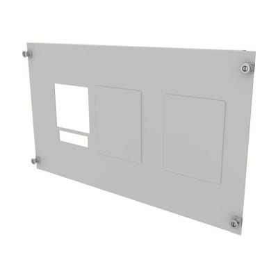
Front plate NZM2X V H300 B600 xE Basic
EP-502332
Eaton
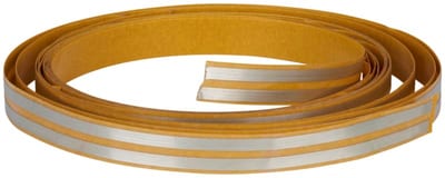
Water Sensor Tape 3 m with Double-Sided Adhesive Tape
CSEZ-01/38
Eaton
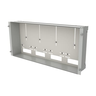
Meter Panel 4 meter H400 B1000 xE Basic (2457649)
Eaton
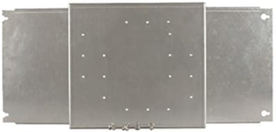
Mounting plate NZM1X V xE B1000
BPZ-MPL-NZM1X-1000-MV
Eaton
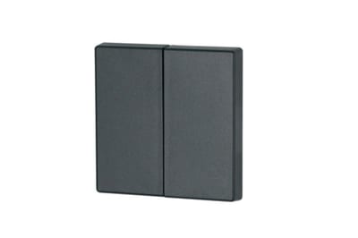
Eaton double rocker anthracite 55x55 mm
126049
Eaton
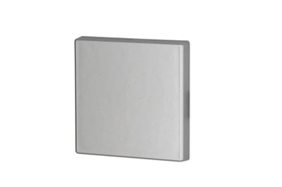
Eaton single rocker silver 55x55 mm
126044
Eaton
Eaton glossy single rocker white 55x55 mm
172985
Technical guides
Catalogue entry last verified: 2026-09-30. A manufacturer datasheet is attached to this entry — confirm application-critical values against it.
Frequently asked questions
- Where can I buy NZMN2-VE100?
- NZMN2-VE100 can be ordered from cballast.com as a Eaton catalogue item: request a quotation on this page or email sales@cballast.com, and the order ships worldwide.
- What is the manufacturer part number for this Eaton product?
- The manufacturer part number is NZMN2-VE100.
- What is the HS code for NZMN2-VE100?
- The customs tariff (HS) code for NZMN2-VE100 is 8536.20.
- Who manufactures NZMN2-VE100?
- NZMN2-VE100 is a Eaton product in the Electrical Components range.
- Is a datasheet available for NZMN2-VE100?
- Yes — the NZMN2-VE100 datasheet can be viewed and downloaded on this page.
- What is the minimum order quantity for NZMN2-VE100?
- The minimum order quantity is 1.
- Is NZMN2-VE100 available?
- Yes — NZMN2-VE100 is available to order: fulfilment is from supplier stock in cBallast's European network, dispatched directly from the warehouse to the customer, with the exact lead time stated in the quotation (reply within 24 hours).