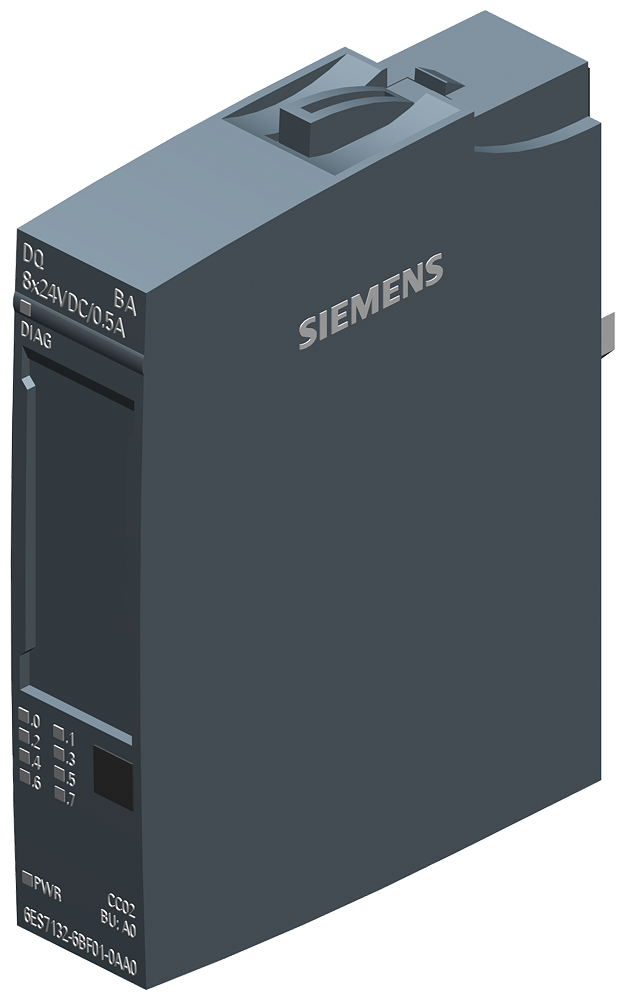
Siemens 6ES7132-6BF01-0AA0 — SIMATIC S7 automation module. Compact controller or expansion module for the S7-1200 or S7-1500 PLC platform. SIMATIC ET 200SP, Digital output module, DQ 8X24VDC/0,5A basic, packaging unit: 1 pcs.
Siemens 6ES7132-6BF01-0AA0 — SIMATIC S7 automation module. Compact controller or expansion module for the S7-1200 or S7-1500 PLC platform. SIMATIC ET 200SP, Digital output module, DQ 8X24VDC/0,5A basic, packaging unit: 1 pcs.
| Manufacturer part number (MPN) | 6ES7132-6BF01-0AA0 |
| EAN / GTIN | 4047623408611 |
| Sales unit | pcs |
| Product type designation | DQ 8x24VDC/0.5A BA |
| HW functional status | From FS02 |
| Firmware version | V0.0 |
| Firmware version — FW update possible | No |
| Usable BaseUnits | BU type A0 |
| Color code for module-specific color-coded label | CC02 |
| Product function — I&M data | Yes; I&M0 to I&M3 |
| Engineering with — STEP 7 TIA Portal configurable/integrated from version | V14 |
| Engineering with — STEP 7 configurable/integrated from version | V5.5 SP3 |
| Engineering with — PROFIBUS from GSD version/GSD revision | One GSD file each, Revision 3 and 5 and higher |
| Engineering with — PROFINET from GSD version/GSD revision | GSDML V2.3 |
| Rated value (DC) | 24 V |
| Permissible range, lower limit (DC) | 19.2 V |
| Permissible range, upper limit (DC) | 28.8 V |
| Reverse polarity protection | Yes |
| Current consumption, max. | 45 mA; without load |
| Power loss, typ. | 1 W |
| Address space per module — Address space per module, max. | 1 byte |
| Selection of BaseUnit for connection variants — 1-wire connection | BU type A0 |
| Selection of BaseUnit for connection variants — 2-wire connection | BU type A0 |
| Selection of BaseUnit for connection variants — 3-wire connection | BU type A0 with AUX terminals or potential distributor module |
| Selection of BaseUnit for connection variants — 4-wire connection | BU type A0 + Potential distributor module |
| Type of digital output | Source output (PNP, current-sourcing) |
| Number of digital outputs | 8 |
| Short-circuit protection | Yes; per channel, electronic |
| Short-circuit protection — Response threshold, typ. | 1 A |
| Limitation of inductive shutdown voltage to | Typ. L+ (-50 V) |
| Switching capacity of the outputs — with resistive load, max. | 0.5 A |
| Switching capacity of the outputs — on lamp load, max. | 5 W |
| Load resistance range — lower limit | 48 Ω |
| Load resistance range — upper limit | 100 kΩ |
| Output current — for signal "1" rated value | 0.5 A |
| Output current — for signal "1" permissible range, max. | 0.5 A |
| Output current — for signal "0" residual current, max. | 10 µA |
| Output delay with resistive load — "0" to "1", max. | 100 µs; at rated load |
| Output delay with resistive load — "1" to "0", max. | 150 µs; at rated load |
| Switching frequency — with resistive load, max. | 100 Hz |
| Switching frequency — with inductive load, max. | 2 Hz |
| Switching frequency — on lamp load, max. | 10 Hz |
| Total current of the outputs — Current per channel, max. | 0.5 A |
| Total current of the outputs — Current per module, max. | 4 A |
| Horizontal installation — up to 60 °C, max. | 4 A |
| Vertical installation — up to 50 °C, max. | 4 A |
| Cable length — shielded, max. | 1 000 m |
| Cable length — unshielded, max. | 600 m |
| Diagnostics indication LED — Monitoring of the supply voltage (PWR-LED) | Yes; green PWR LED |
| Diagnostics indication LED — Channel status display | Yes; green LED |
| Isolation tested with | 707 V DC (type test) |
| Suitable for safety-related tripping of standard modules | Yes; see FAQ Entry ID: 39198632 |
| Highest safety class achievable in safety mode — SIL acc. to IEC 61508 | SIL 2 |
| Ambient temperature during operation — horizontal installation, min. | -30 °C; < 0 °C as of FS02 |
| Ambient temperature during operation — horizontal installation, max. | 60 °C |
| Ambient temperature during operation — vertical installation, min. | -30 °C; < 0 °C as of FS02 |
| Ambient temperature during operation — vertical installation, max. | 50 °C |
| Altitude during operation relating to sea level — Installation altitude above sea level, max. | 5 000 m; Restrictions for installation altitudes > 2 000 m, see manual |
| Absolute humidity — dew point, min. | -60 °C; suitable for dry room applications |
| Dimensions — Width | 15 mm |
| Dimensions — Height | 73 mm |
| Dimensions — Depth | 58 mm |
| Weight, approx. | 30 g |
| Supporting protocol for EtherCAT | Yes |
| Supply voltage DC | 19.2–28.8 V |
| Voltage type (supply voltage) | DC |
| Digital inputs configurable | No |
| Digital outputs configurable | Yes |
| Type of voltage (input voltage) | DC |
| Output current | 0.5 A |
| Permitted voltage at output | 19.2–28.8 V |
| Type of output voltage | DC |
| Short-circuit protection, outputs available | Yes |
| With optical interface | No |
| Supporting protocol for TCP/IP | No |
| Supporting protocol for PROFIBUS | No |
| Supporting protocol for CAN | No |
| Supporting protocol for INTERBUS | No |
| Supporting protocol for ASI | No |
| Supporting protocol for KNX | No |
| Supporting protocol for Modbus | No |
| Supporting protocol for Data-Highway | No |
| Supporting protocol for DeviceNet | No |
| Supporting protocol for SUCONET | No |
| Supporting protocol for LON | No |
| Supporting protocol for PROFINET IO | No |
| Supporting protocol for PROFINET CBA | No |
| Supporting protocol for SERCOS | No |
| Supporting protocol for Foundation Fieldbus | No |
| Supporting protocol for EtherNet/IP | No |
| Supporting protocol for AS-Interface Safety at Work | No |
| Supporting protocol for DeviceNet Safety | No |
| Supporting protocol for INTERBUS-Safety | No |
| Supporting protocol for PROFIsafe | No |
| Supporting protocol for SafetyBUS p | No |
| Supporting protocol for other bus systems | No |
| Radio standard Bluetooth | No |
| Radio standard WLAN 802.11 | No |
| Radio standard GPRS | No |
| Radio standard GSM | No |
| Mobile communications standard 3G (UMTS) | No |
| IO link master | No |
| System accessory | Yes |
| Degree of protection (IP) | IP20 |
| Type of electric connection | Spring clamp connection |
| Time delay at signal change | 0.1–0.15 ms |
| Fieldbus connection over separate bus coupler possible | Yes |
| Suitable for rail mounting | Yes |
| Wall mounting/direct mounting | No |
| Front built-in possible | Yes |
| Rack-assembly possible | Yes |
| Suitable for safety functions | No |
| SIL according to IEC 61508 | 2 |
| Performance level according to EN ISO 13849-1 | Level d |
| Appendant operation agent (Ex ia) | No |
| Explosion safety category for gas | ATEX gas-ex-protection, Cat. 3G |
| Explosion safety category for dust | None |
| Width | 15 mm |
| Height | 73 mm |
| Depth | 58 mm |
| Country of origin | Germany |
| MOQ | 1 |