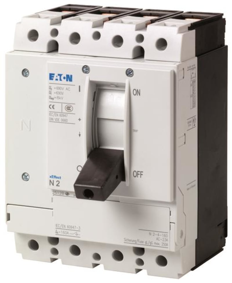
| Manufacturer part number (MPN) | N2-4-160-S1-DC |
| EAN / GTIN | 4015081251421 |
| Sales unit | pcs |
| Eaton catalogue number | 127732 |
| Depth | 149 mm |
| Height | 184 mm |
| Width | 140 mm |
| Weight | 2.87 kg |
| Compliances | RoHS conform |
| Certifications | IEC |
| Functions | Interlockable; Photovoltaic applications; Voltage release optional; Disconnectors/main switches |
| Amperage Rating | 160 A |
| Application | Open areas Utility buildings |
| Circuit breaker frame type | N2 |
| Features | Version as maintenance-/service switch; Version as main switch; Remote operation with shunt releases / remote operator; Version as emergency stop installation; Motor drive optional |
| Number of poles | Four-pole |
| Type | DC switch-disconnector |
| Ambient operating temperature - max | 70 °C |
| Ambient storage temperature - max | 70 °C |
| Ambient operating temperature - min | -25 °C |
| Equipment heat dissipation, current-dependent | 27 W |
| Rated operational current for specified heat dissipation (In) | 160 A |
| Current rating (Iu) at 40°C with terminal jumpers | 160 A |
| Current rating (Iu) at 65°C with terminal jumpers | 160 A |
| Electrical connection type of main circuit | Screw connection |
| Handle type | Rocker lever |
| Number of operations per hour - max | 120 |
| Overvoltage category | III |
| Pollution degree | 3 |
| Rated conditional short-circuit current with back-up fuse | 15 kA at 1000 V; 200 AgR |
| Rated insulation voltage (Ui) | 1250 V |
| Rated operational current | 160 A (DC 22-A) |
| Rated short-time withstand current (Icw) | 3.6 kA |
| Rated short-time withstand current (t = 1 s) | 3.6 kA |
| Short-circuit protective device fuses - max | 200 A gR |
| Utilization category | DC-22 A |
| Voltage rating | 1000 V - 1000 V |
| Degree of protection | Other |
| Degree of protection (IP), front side | IP20 |
| Handle color | Black |
| Lifespan, mechanical | 20000 operations |
| Mounting Method | Distribution board installation; Built-in device fixed built-in technique; Intermediate mounting; Ground mounting; Fixed |
| Number of auxiliary contacts (change-over contacts) | 0 |
| Number of auxiliary contacts (normally closed contacts) | 0 |
| Number of auxiliary contacts (normally open contacts) | 0 |
| Number of switches | 1 |
| Switch positions | I, +, 0 |
| Standard terminals | Screw terminal |
| Terminal capacity (aluminum solid conductor/cable) | 16 mm² (1x) at tunnel terminal |
| Terminal capacity (aluminum stranded conductor/cable) | 25 mm² - 185 mm² (1x) at tunnel terminal |
| Terminal capacity (copper busbar) | Min. 16 mm x 5 mm direct at switch rear-side connection; M8 at rear-side screw connection; Max. 24 mm x 8 mm direct at switch rear-side connection |
| Terminal capacity (copper solid conductor/cable) | 10 mm² - 16 mm² (1x) direct at switch rear-side connection; 4 mm² - 16 mm² (2x) direct at switch rear-side connection; 4 mm² - 16 mm² (2x) at box terminal; 4 mm² - 16 mm² (1x) at box terminal; 16 mm² (1x) at tunnel terminal |
| Terminal capacity (copper stranded conductor/cable) | 25 mm² - 185 mm² (1x) at tunnel terminal; 25 mm² - 185 mm² (1x) at box terminal; 25 mm² - 70 mm² (2x) at box terminal; 25 mm² - 185 mm² (1x) direct at switch rear-side connection; 25 mm² - 70 mm² (2x) direct at switch rear-side connection |
| Terminal capacity (copper strip) | Min. 2 segements of 16 mm x 0.8 mm at rear-side connection (punched); Max. 10 segments of 16 mm x 0.8 mm at box terminal; Max. 10 segments of 24 mm x 0.8 mm at rear-side connection (punched); Min. 2 segments of 9 mm x 0.8 mm at box terminal; Max. 8 segments of 15.5 mm x 0.8 mm (2x) at box terminal |
| Document Name | Description Action |
| Country of origin | Romania |