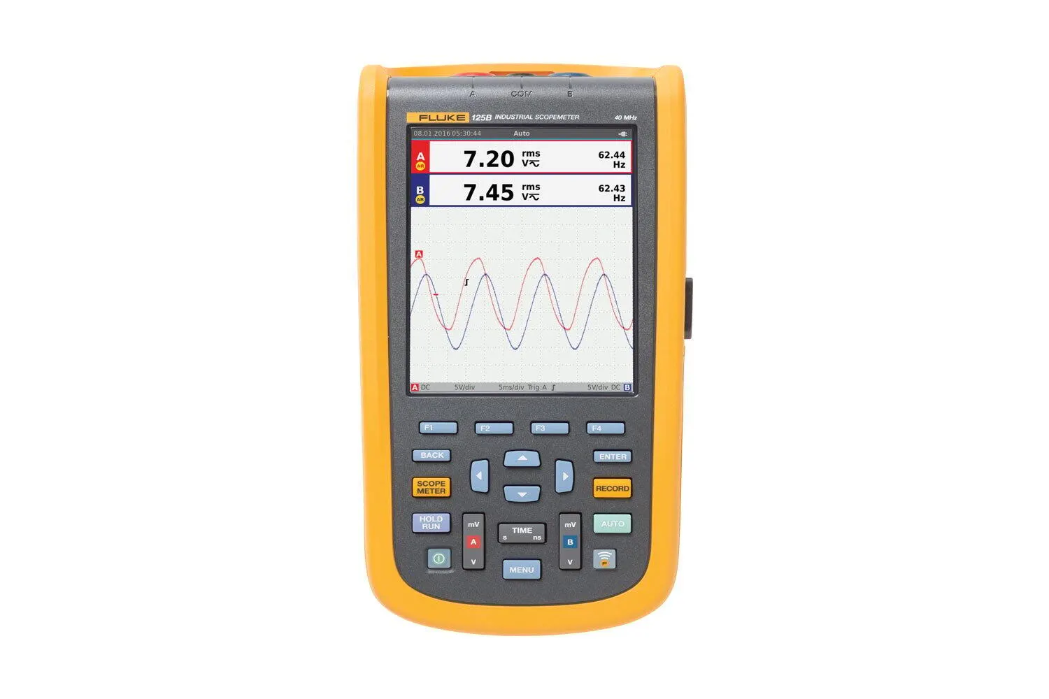
The Fluke 120B Series is a handheld digital oscilloscope for industrial electrical & electro-mechanical equipment troubleshooting & maintenance.
The Fluke 120B Series is a handheld digital oscilloscope for industrial electrical & electro-mechanical equipment troubleshooting & maintenance.
| Manufacturer part number (MPN) | 4755829 Brand: Fluke Category: Tools Without probes and test leads (with BB120): 123B: dc to 20 MHz (-3 dB) 124B and 125B: dc to 40 MHz (-3 dB) Without probes and test leads: <10 Hz (-3 dB) Rise time, excluding probes, test leads: 123B <17.5 ns 124B and 125B <8.75 ns Input impedance Without probes and test leads: 1 MΩ//20 pF Input impedance With BB120: 1 MΩ//24 pF Sensitivity: 5 mV to 200 V/div analogue bandwidth limiter: 10 kHz Display modes: A, -A, B, -B Direct, with test leads, or with VP41 Probe: 600 Vrms Cat IV, 750 Vrms maximum voltage. Max. input voltage A and B With BB120: 600 Vrms Max. floating voltage, from any terminal to ground: 600 Vrms Cat IV, 750 Vrms up to 400Hz Scope modes: Normal, Single, Roll Ranges (normal) Equivalent sampling: 123B: 20 ns to 500 ns/div |
| Ranges (normal) Real time sampling | 1 μs to 5 s/div Ranges (normal) Single (real time): 1 μs to 5 s/div Ranges (normal) Roll (real time): 1s to 60 s/div Equivalent sampling (repetitive signals): Up to 4 GS/s Real time sampling 1 μs to 60 s/div: 40 MS/s Screen update: Free run, on trigger Source: A, B Sensitivity A and B @ DC to 5 MHz: 0.5 divisions or 5 mV Sensitivity A and B @ 40 MHz: 123B: 4 divisions Sensitivity A and B @ 60 MHz: 123B: N/A Sensitivity A and B Slope: Positive, negative Display modes Normal: Captures up to 25 ns glitches and displays analogue-like persistence waveform Display modes Smooth: Suppresses noise from a waveform Display modes Glitch off: Does not capture glitches between samples Display modes Envelope: Records and displays the minimum and maximum of waveforms over time Auto set (Connect-and-View™): Continuous fully automatic adjustments of amplitude, time base, trigger levels, trigger gap, and hold-off. Manual override by user adjustment of amplitude, time base, or trigger level |
| Ranges | 500 mV, 5 V, 50 V, 500 V, 750 V Accuracy: ±(0.5% +5 counts) Common mode rejection (CMRR): >100 dB @ dc, >60 dB @ 50, 60, or 400 Hz Full scale reading: 5000 counts DC to 60 Hz (V ac+dc): ±(1% +10 counts) 1 Hz to 60 Hz (V ac): ±(1% +10 counts) 60 Hz to 20 kHz: ±(2.5% +15 counts) DC rejection (only VAC): >50 dB Modes: Max peak, Min peak, or pk-to-pk Accuracy Accuracy Max peak or Min peak: 5% of full scale Accuracy Accuracy Peak-to-Peak: 10% of full scale Frequency range: 15 Hz (1 Hz) to 50 MHz in continuous autoset Accuracy @1 Hz to 1 MHz: ±(0.5% +2 counts) Max reading: 50.00 kRPM Range: 2% to 98% With current clamp Ranges: Same as V dc, V ac, V ac+dc, or PEAK With current clamp Scale factors: 0.1 mV/A, 1 mV/A, 10 mV/A, 100 mV/A, 400 mV/A, 1 V/A, 10 mV/mA With current clamp Accuracy: Same as V dc, V ac, V ac+dc, or PEAK (add current clamp uncertainty) Scale factor: 1 mV/°C and 1 mV/°F 0 dBV: 1 V 0 dBm (600 Ω /50 Ω): 1 mW referenced to 600 Ω or 50 Ω dB on: V dc, V ac, or Vac+dc Resolution: 1 degree Configurations: 1 phase / 3 phase 3 conductor balanced loads (3 phase: fundamental component only, AUTOSET mode only) Power factor (PF): Ratio between watts and VA range - 0.00 to 1.00 Watt: RMS reading of multiplying corresponding samples of input A (volts) and input B (amperes) VA: Vrms x Arms VA reactive (var): √((VA)2-W2) Purpose: To measure on pulse width modulated signals, like motor drive inverter outputs Principle: Readings show the effective voltage based on the average value of samples over a whole number of periods of the fundamental frequency Ranges 123B and 124B: 500 Ω , 5 kΩ, 50 kΩ, 500 kΩ, 5 MΩ, 30 MΩ Ranges 125B: 50 Ω, 500 Ω , 5 kΩ, 50 kΩ, 500 kΩ, 5 MΩ, 30 MΩ Measurement current: 0.5 mA to 50 nA, decreases with increasing ranges Open circuit voltage: <4 V Beep: <(30 Ω ±5 Ω) in 50 Ω range Detection of shorts of: ≥1 ms Measurement voltage @0.5 mA: >2.8 V Measurement voltage @open circuit: <4 V Polarity: + on input A, - on COM Zero Set: Set actual value to reference AutoHold (on A): Captures and freezes a stable measurement result. Beeps when stable. AutoHold works on the main meter reading, with thresholds of 1 Vpp for AC signals and 100 mV for DC signals |
| Fixed decimal point | Activated by using attenuation keys Sources: A |
| B Single vertical line | Average, min and max readout Dual vertical lines: Peak-peak, time distance and reciprocal time distance readout Dual horizontal lines: High, low and peak-peak readout Rise or fall time: Transition time, 0%-level and 100%-level readout (manual or auto leveling; auto leveling only possible in single channel mode) Measurement Speed: Maximum 2 measurement/s Record Size (min, max, average): 2 M readings for 1 channel Recorded Time Span: 2 weeks Maximum number of events: 1024 Maximum sample rate: 400 K sample/s Size Internal memory: 400 M samples Recorded Time Span internal memory: 15 minutes at 500 μs/div 11 hours at 20 ms/div Record Size SD card: 1.5 G samples Recorded Time Span SD card: 11 hours at 500 μs/div 14 days at 20 ms/div Readings: Watt, VA, var, PF, DPF, Hz Watt, VA, var ranges (auto): 250 W to 250 MW, 625 MW, 1.56 GW DPF: 0.00 to 1.00 PF: 0.00 to 1.00, ±0.04 Number of Harmonics: DC to 51 Vrms / Arms /Watt: Each harmonic from fundamental maybe selected for individual readings Type Subtype: Protocol AS-i: NEN-EN50295 CAN: ISO-11898 Interbus S RS-422: EIA-422 Modbus RS-232: RS-232/EIA-232 Modbus RS-485: RS-485/EIA-485 Foundation Fieldbus H1: 61158 type 1, 31.25 kBit Profibus DP: EIA-485 Profibus PA: 61158 type 1 Display Type: 5.7-inch color active matrix TFT Display Resolution: 640 x 480 pixels Waveform Display Vertical: 10 div of 40 pixels Waveform Display Horizontal: 12 div of 40 pixels Power External: Via Power Adapter BC430 Power Input voltage: 10 V DC to 21 V DC Power Power consumption: 5 W typical Power Input connector: 5 mm jack Power Internal: Via Battery Pack BP290 Power Battery power: Rechargeable Li-Ion 10.8 V Power Operating time: 7 hours with 50% backlight brightness Power Charging time: 4 hours with test tool off, 7 hours with test tool on Power Allowable ambient temp: 0 to 40 °C (32 to 104 °F) during charging Mechanical Size: 259 x 132 x 55 mm (10.2 x 5.2 x 2.15 in) Mechanical Weight: 1.4 kg (3.2 lb) including battery pack Interface Optically isolated: Transfer screen copies (bitmaps), settings and data Interface USB to PC/laptop: OC4USB optically isolated USB adapter/cable, (optional), using FlukeView® software for Windows® |
| Interface Optional WiFi adapter | Fast transfer of screen copies (bitmaps), settings and data to PC/laptop, tablet, smartphone, etc. A USB port is provided for attaching the WiFi dongle. Do not use the USB port with a cable for safety reasons |
| Environmental | MIL-PRF-28800F, Class 2 Temperature Battery Operation: 0 to 40 °C (32 to 104 °F) Temperature Power Adapter Operation: 0 to 50 °C (32 to 122 °F) Temperature Storage: -20 to 60 °C (-4 to 140 °F) Humidity (Operating) @ 0 to 10 °C (32 to 50 °F): Non-condensing Humidity (Operating) @ 10 to 30 °C (50 to 86 °F): 95% Humidity (Operating) @ 30 to 40 °C (86 to 104 °F): 75% Humidity (Operating) @ 40 to 50 °C (104 to 122 °F): 45% Storage @ -20 to 60 °C (-4 to 140 °F): Non-condensing Altitude Operating at 3 km (10,000 feet): CAT III 600 V Altitude Operating at 2 km (6,600 feet): CAT IV 600 V Altitude Storage: 12 km (40,000 feet) EMC electromagnetic compatibility International: IEC 61326-1: Industrial |
| CISPR 11 | Group 1, Class A EMC electromagnetic compatibility Korea (KCC): Class A Equipment (Industrial Broadcasting & Communication Equipment) EMC electromagnetic compatibility USA (FCC): 47 CFR 15 subpart B. This product is considered an exempt device per clause 15.103. Wireless radio with adapter Frequency range: 2412 MHz to 2462 MHz Wireless radio with adapter Output power: <100 mW Enclosure protection: IP51, ref: EN/IEC60529 Safety General: IEC 61010-1: Pollution Degree 2 Safety Measurement: IEC 61010-2-033: CAT IV 600 V/CAT III 750 V Direct on input or with leads: 600 Vrms CAT IV for derating With Banana-to-BNC Adapter BB120: 600 Vrms for derating |
| MOQ | 1 |