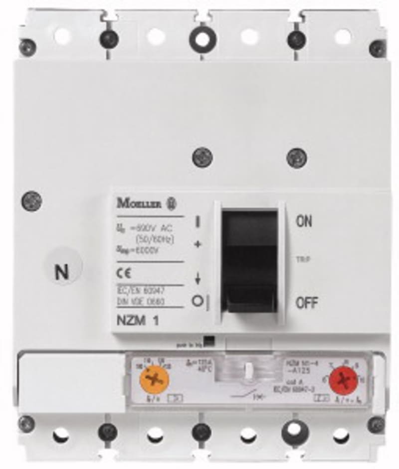
| Manufacturer part number (MPN) | NZMB1-4-A20 |
| Series | Eaton NZM1 (Moeller series NZM) |
| Type | Molded-case circuit breaker (MCCB) |
| Breaking-capacity class | B (basic breaking capacity) |
| Number of poles | 4-Pole |
| Rated current (In) | 20 A |
| Frame size | NZM1 (up to 160 A) |
| Rated operational voltage (Ue) | 690 V AC |
| Rated insulation voltage (Ui) | 800 V |
| Rated ultimate short-circuit breaking capacity (Icu) at 400/415 V AC | 25 kA |
| Trip unit / release | Thermomagnetic release — adjustable thermal overload and electromagnetic short-circuit protection |
| Utilization category | A |
| Suitable for isolation | Yes |
| Standard | IEC/EN 60947-2 |
| EAN / GTIN | 4015082812379 |
| HS code | 8536.20 |
| Sales unit | pcs |
| Eaton catalogue number | 281237 |
| Depth | 84.5 mm |
| Height | 145 mm |
| Width | 120 mm |
| Weight | 1.334 kg |
| Compliances | RoHS conform |
| Certifications | IEC/EN 60947; IEC |
| Functions | System and cable protection |
| Amperage Rating | 20 A |
| Application | Use in unearthed supply systems at 440 V |
| Circuit breaker frame type | NZM1 |
| Features | Protection unit |
| Release system | Thermomagnetic release |
| Used with | Enclosure 100 x 600 x 1000 mm |
| Ambient operating temperature - max | 70 °C |
| Ambient storage temperature - max | 70 °C |
| Ambient operating temperature - min | -25 °C |
| Equipment heat dissipation, current-dependent | 9.82 W |
| Rated operational current for specified heat dissipation (In) | 20 A |
| Current rating of neutral conductor | 200% of phase conductor |
| Direction of incoming supply | As required |
| Electrical connection type of main circuit | Frame clamp |
| Handle type | Rocker lever |
| Instantaneous current setting (Ii) - max | 350 A |
| Instantaneous current setting (Ii) - min | 350 A |
| Isolation | 500 V AC (between auxiliary contacts and main contacts); 300 V AC (between the auxiliary contacts) |
| Lifespan, electrical | 7500 operations at 400 V AC-1; 7500 operations at 415 V AC-1 |
| Number of operations per hour - max | 120 |
| Overload current setting (Ir) | 15 A - 20 A |
| Overload current setting (Ir) - max | 20 A |
| Overload current setting (Ir) - min | 15 A |
| Overvoltage category | III |
| Pollution degree | 3 |
| Rated impulse withstand voltage (Uimp) at auxiliary contacts | 6000 V |
| Rated impulse withstand voltage (Uimp) at main contacts | 6000 V |
| Rated short-circuit making capacity Icm at 240 V |
| 50/60 Hz | 63 kA |
| Rated short-circuit making capacity Icm at 400/415 V |
| 50/60 Hz | 53 kA |
| Rated short-circuit making capacity Icm at 440 V |
| Short-circuit release non-delayed setting - max | 350 A |
| Short-circuit release non-delayed setting - min | 350 A |
| Short-circuit total breaktime | < 10 ms |
| Voltage rating | 440 V - 440 V |
| Climatic proofing | Damp heat, constant, to IEC 60068-2-78; Damp heat, cyclic, to IEC 60068-2-30 |
| Degree of protection | IP20 (basic degree of protection, in the operating controls area); IP20 |
| Degree of protection (IP), front side | IP66 (with door coupling rotary handle); IP40 (with insulating surround) |
| Degree of protection (terminations) | IP00 (terminations, phase insulator and strip terminal); IP10 (tunnel terminal) |
| Lifespan, mechanical | 20000 operations |
| Mounting Method | Built-in device fixed built-in technique; Fixed; DIN rail (top hat rail) mounting optional |
| Number of auxiliary contacts (change-over contacts) | 0 |
| Number of auxiliary contacts (normally closed contacts) | 0 |
| Number of auxiliary contacts (normally open contacts) | 0 |
| Position of connection for main current circuit | Front side |
| Protection against direct contact | Finger and back-of-hand proof to DIN EN 50274/VDE 0106 part 110 |
| Shock resistance | 20 g (half-sinusoidal shock 20 ms) |
| Optional terminals | Connection on rear. Screw terminal. Tunnel terminal |
| Standard terminals | Box terminal |
| Terminal capacity (aluminum solid conductor/cable) | 10 mm² - 16 mm² (2x) direct at switch rear-side connection; 16 mm² (1x) at tunnel terminal; 10 mm² - 16 mm² (1x) direct at switch rear-side connection |
| Terminal capacity (aluminum stranded conductor/cable) | 25 mm² - 35 mm² (1x) direct at switch rear-side connection; 25 mm² - 35 mm² (2x) direct at switch rear-side connection; 25 mm² - 95 mm² (1x) at tunnel terminal |
| Terminal capacity (control cable) | 0.75 mm² - 2.5 mm² (1x); 0.75 mm² - 1.5 mm² (2x) |
| Terminal capacity (copper busbar) | M6 at rear-side screw connection; Min. 12 mm x 5 mm direct at switch rear-side connection; Max. 16 mm x 5 mm direct at switch rear-side connection |
| Terminal capacity (copper solid conductor/cable) | 6 mm² - 16 mm² (1x) direct at switch rear-side connection; 6 mm² - 16 mm² (1x) at box terminal; 16 mm² (1x) at tunnel terminal; 4 mm² - 16 mm² (2x) at box terminal; 4 mm² - 16 mm² (2x) direct at switch rear-side connection |
| Terminal capacity (copper stranded conductor/cable) | 25 mm² - 95 mm² (1x) at 1-hole tunnel terminal; 6 mm² - 70 mm² (1x) direct at switch rear-side connection; 6 mm² - 70 mm² (1x) at box terminal; 4 mm² - 25 mm² (2x) direct at switch rear-side connection; 4 mm² - 25 mm² (2x) at box terminal |
| Terminal capacity (copper strip) | Min. 2 segments of 9 mm x 0.8 mm at box terminal; Max. 9 segments of 9 mm x 0.8 mm at box terminal |