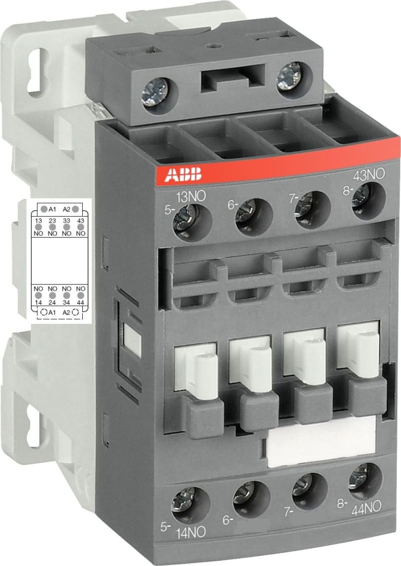
| Manufacturer part number (MPN) | NFZ40E-22 |
| EAN / GTIN | 3471523101623 |
| Sales unit | pcs |
| Country of Origin | India |
| Product Sales Status | Active |
| Product Net Width | 45 mm |
| Product Net Depth / Length | 77 mm |
| Product Net Height | 86 mm |
| Number of Auxiliary Contacts NO | 4 |
| Number of Auxiliary Contacts NC | 0 |
| Number of Poles | 4P |
| Standards | IEC/EN 60947-1, IEC/EN 60947-5-1, UL 60335-2-40 LZGH2 A2L, UL 508, CSA C22.2 No. 60335-2-40 LZGH2 A2L, CSA C22.2 No. 14-13 |
| Rated Operational Voltage | Auxiliary Circuit 690 V |
| Rated Frequency (f) | Auxiliary Circuit 50 / 60 Hz; Control Circuit 50 / 60 Hz |
| Conventional Free-air Thermal Current (I th ) | acc. to IEC 60947-5-1, Θ = 40 °C 16 A |
| Rated Operational Current AC-15 (I e ) | (500 V) 2 A; (690 V) 2 A; (24 / 127 V) 6 A; (220 / 240 V) 4 A; (400 / 440 V) 3 A |
| Rated Operational Current DC-13 (I e ) | (24 V) 6 A / 144 W; (48 V) 2.8 A / 134 W; (72 V) 1 A / 72 W; (110 V) 0.55 A / 60 W; (125 V) 0.55 A / 69 W; (220 V) 0.27 A / 60 W; (250 V) 0.27 A / 68 W; (400 V) 0.15 A / 60 W; (500 V) 0.13 A / 65 W; (600 V) 0.1 A / 60 W |
| Rated Short-time Withstand Current Low Voltage (I cw ) | for 0.1 s 140 A; for 1 s 100 A |
| Rated Insulation Voltage (U i ) | acc. to IEC 60947-5-1 690 V; acc. to UL/CSA 600 V |
| Rated Impulse Withstand Voltage (U imp ) | 6 kV |
| Maximum Electrical Switching Frequency | (AC-15) 1200 cycles per hour; (DC-13) 900 cycles per hour |
| Maximum Mechanical Switching Frequency | 6000 cycles per hour |
| Rated Control Circuit Voltage (U c ) | 50 Hz 48 ... 130 V; 60 Hz 48 ... 130 V; DC Operation 48 ... 130 V |
| Power Loss | at 6 A per Pole 0.1 W |
| Operate Time | Between Coil De-energization and NC Contact Closing 13 ... 98 ms; Between Coil De-energization and NO Contact Opening 11 ... 95 ms; Between Coil Energization and NC Contact Opening 38 ... 90 ms; Between Coil Energization and NO Contact Closing 40 ... 95 ms |
| Mounting on DIN Rail | TH35-15 (35 x 15 mm Mounting Rail) acc. to IEC 60715; TH35-7.5 (35 x 7.5 mm Mounting Rail) acc. to IEC 60715 |
| Mounting by Screws (not supplied) | 2 x M4 Screws Placed Diagonally |
| Connecting Capacity Auxiliary Circuit | Flexible with Ferrule 1/2x 0.75 ... 2.5 mm²; Flexible with Insulated Ferrule 1x 0.75 ... 2.5 mm²; Flexible with Insulated Ferrule 2x 0.75 ... 1.5 mm²; Rigid Solid 1/2x 1 ... 2.5 mm²; Rigid Stranded 1/2x 1 ... 2.5 mm² |
| Connecting Capacity Control Circuit | Flexible with Ferrule 1/2x 0.75 ... 2.5 mm²; Flexible with Insulated Ferrule 1x 0.75 ... 2.5 mm²; Flexible with Insulated Ferrule 2x 0.75 ... 1.5 mm²; Rigid Solid 1/2x 1 ... 2.5 mm²; Rigid Stranded 1/2x 1 ... 2.5 mm² |
| Wire Stripping Length | Auxiliary Circuit 10 mm; Control Circuit 10 mm |
| Degree of Protection | acc. to IEC 60529, IEC 60947-1, EN 60529 Auxiliary Terminals IP20; acc. to IEC 60529, IEC 60947-1, EN 60529 Coil Terminals IP20 |
| Tightening Torque | Auxiliary Circuit 1.2 N·m; Control Circuit 1.2 N·m |
| Terminal Type | Screw Terminals |
| Connecting Capacity Auxiliary Circuit UL/CSA | Rigid Solid 1/2x 18-14 AWG; Rigid Stranded 1/2x 18-14 AWG |
| Tightening Torque UL/CSA | Auxiliary Circuit 11 in·lb; Control Circuit 11 in·lb |
| Ambient Air Temperature | Close to Contactor for Storage -60 ... +80 °C; Near Contactor for Operation in Free Air -40 ... 70 °C |
| Climatic Withstand | Category B according to IEC 60947-1 Annex Q |
| Maximum Operating Altitude Permissible | Without Derating 3000 m |
| Resistance to Shock acc. to IEC 60068-2-27 | Closed |
| Shock Direction | B1 25 g; Open |
| Shock Direction | B1 5 g; Shock Direction: A 30 g; Shock Direction: B2 15 g; Shock Direction: C1 25 g; Shock Direction: C2 25 g |
| Resistance to Vibrations | 4g Closed Position & 2g Open position 5 ... 300 Hz |
| Pollution Degree | 3 |
| ABB EcoSolutions | Yes |
| ABB Site Meeting Group Waste To Landfill Target | No non-hazardous waste is sent to a landfill |
| EcoSolutions Profile | 1SBC100156C0308 |
| End Of Life Disassembling Instructions | 1SBC101080M6801 |
| Environmental Product Declaration - EPD | 1SBD250584E3000 |
| Improved Energy Efficiency for Customers | Product Efficiency - Product considered more energy-efficient compared to similar product on market or older products from the same line |
| Recyclability Rate of the Product acc. to EN45555 | Design for Closing Resource Loops - Standard EN45555 - 92.7 % |
| A2L Certificate – UL | 9AKK108469A4900; 9AKK108469A4902 |
| ABS Certificate | ABS_26-0348269-PDA_FR; ABS_26-0348269-PDA-DUP_CN |
| BV Certificate | BV_2634H24899C1 |
| CB Certificate | CB_SE-117902 |
| CCC Certificate | CCC_2024010303656666 |
| Declaration of Conformity - CCC | CQC2011010303465426 |
| Declaration of Conformity - CE | 1SBD250005U1000 |
| Declaration of Conformity - UKCA | 1SBD250036U1000 |
| DNV Certificate | DNV_TAE00001BV-5 |
| LR Certificate | LRS_LR2003684TA-02 |
| RINA Certificate | RINA_ELE142224XG |
| RMRS Certificate | RMRS_1802702280 |
| UL Certificate | UL_20180227_E252354_2_1 |
| UL Listing Card | UL_E252354 |
| Object Classification Code | K |
| ETIM 7 | EC000196 - Contactor relay |
| eClass | V11.0 : 27371001 |
| UNSPSC | 39121529 |
| IDEA Granular Category Code (IGCC) | 4763 >> Power contactor, DC switching |
| E-Number (Finland) | 3706419 |
| E-Number (Sweden) | 3211462 |